The Vulkan Shader Binding Table (SBT) confused me a lot when I first started learning about it. The high-level concept is fairly simple, but complexity arises with Vulkan's implementation of it. The SBT is a necessary part of the Vulkan ray tracing pipeline. Whenever we traverse a ray in the ray tracing pipeline, we use the SBT to determine which shaders to invoke for different acceleration structure instances. Where this gets tricky is how we offset into the SBT.
I found that the offsets were confusing mainly due to the fact that they're set in 3 different locations. They're set once in VkAccelerationStructureInstanceKHR{} (host-side), once in traceRayEXT() (device-side), and once in vkCmdTraceRaysKHR() (host-side). These 3 offsets are then combined to create a final offset into the SBT. Before discussing offsets, let's look at the usual layout of a SBT. The following image was taken from Johannes Unterguggenberger's slides.
As you can see, we index into the rows of the SBT. Each row can have up to 3 shaders, depending on what it's meant for. There are 3 main types of shaders that we care about: Ray generation shaders, miss shaders, and hit groups (which are tuples of closest-hit, any-hit, and intersection shaders).
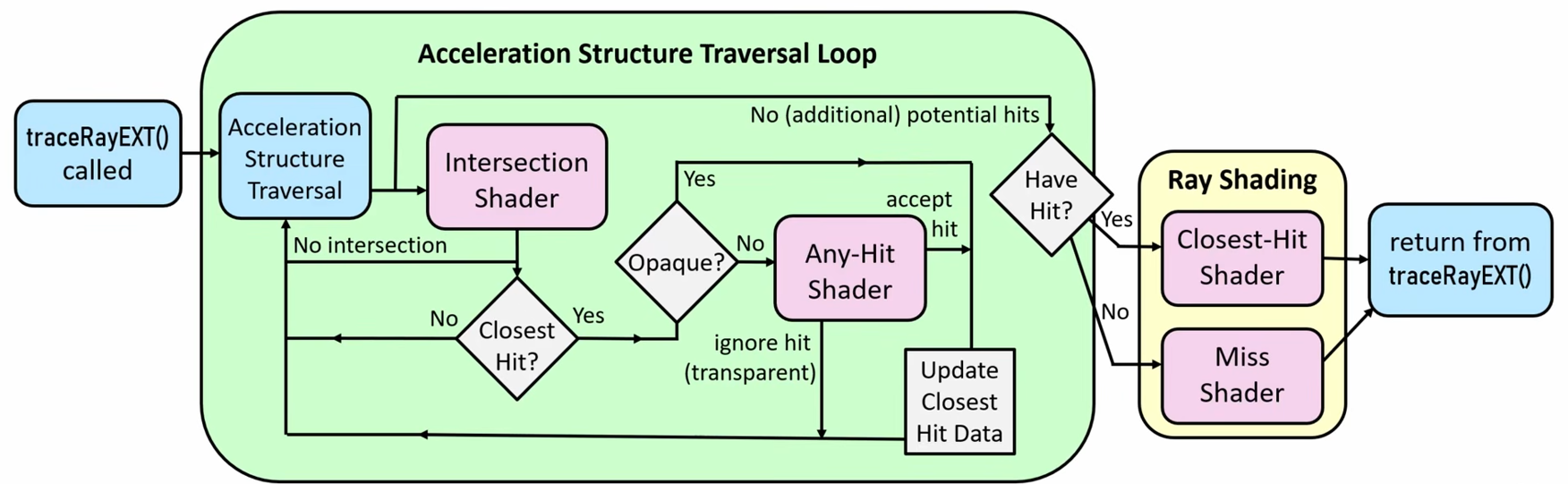
Ray generation and miss shaders are pretty self-explanatory in what they're meant for. Intersection shaders are used mainly for procedural or custom geometry. Since ray-triangle intersetions are so common, Vulkan already knows how to do this, and you do not need to write an intersection shader. What Vulkan doesn't know is how to intersect a sphere, for example, so you would have to create a custom ray-sphere intersection shader.
Any-hit shaders are typically used when we encounter a candidate intersection. An intersection is usually a "candidate" instead of an actual "hit" due to opacity. A common example is to consider leaves or grass. We usually do this with something like an alpha texture on a quad, but a lot of the alpha texture will be transparent. Just because we hit the quad doesn't mean the ray actually hit the grass/leaf, it could have just hit the transparent part. An any-hit shader will answer the question of whether this to accept or reject a candidate intersection.
Once the acceleration structure traversal loop is over, we run either a closest-hit shader or a miss shader depending on whether we found an intersection. The closest-hit shader takes the intersection as input and determines the final color at that location. The miss shader will calculate a color based on the fact that no intersection was found, e.g. sampling a skybox. The following diagram in Johannes Unterguggenberger's slides does a good job showing the ray tracing pipeline in depth:
Note that there are also such things as callable shaders, unfortunately the spec seems to speak very little about them. From what I could gather, callable shaders are a way to do subroutine work without incurring the wrath of GPU divergence. This Reddit post seems to talk about a bit more. For example, imagine you have a closest-hit shader which does the following things:
- Find where the ray hit
- Get the surface normal
- Get the material index
- Evaluate the material's BSDF
- Trace any additional rays (reflection/refraction)
- Return the result
Now suppose our group/warp consists of 32 threads, where 30 of them have material A (easy to evaluate BSDF), and 2 of them have material B (hard to evaluate BSDF). If you're familiar with how the GPU processes groups, you'll know that it can't simply evaluate the BSDF's of both materials in parallel. Instead, it sequentially has to evaluate all threads of one material, then all threads of the other (depending on the GPU, it might even be sequenced as one thread of one material, followed by one thread of another, back-and-forth until all threads are completed). This is what we call divergence. It would typically show up as an if-then-else in the closest-hit shader:
// Closest-hit shader
void main() {
    // ...
    if (material.type == MAT_A)
    {
        bsdf = materialA_BSDF(normal, incoming, ... /* Any other params */);
    } else if (material.type == MAT_B)
    {
        bsdf = materialB_BSDF(normal, incoming, ... /* Any other params */);
    } else if (...) {
        // Any other materials
    } else {
        // Default material
    }
    // ...
}
To get around this, we can create separate callable shaders for each material, such as callable_mat_a.glsl and callable_mat_b.glsl. This allows the implementation to group together the shader calls from multiple work groups. For example, instead of 8 groups where each group has 28 material A threads and 4 material B threads, we could create a single group with 32 material B therads (and importantly, no divergence!). In the closest-hit shader, we would just need to call executeCallableEXT(index) instead of the if-then-else, where the index is into the callable SBT records. We would need to also pass some payload which gets populated by the callable shader, but before explaining how payloads work, we'll talk about ray generation shaders since it's also applicable to them.
Ray Generation Shaders
Each shader naturally has an important part to play in the overall pipeline. Ray generation shaders are the most straightforward. Their main job is to call the traceRayEXT() function given a ray's parameters and an acceleration structure. As the name implies, this function traces a single ray through the acceleration structure and determines the resulting color. Let's look at the function in more detail:
void traceRayEXT(
    accelerationStructureEXT topLevel,
    uint rayFlags,
    uint cullMask,
    uint sbtRecordOffset, // SBT
    uint sbtRecordStride, // SBT
    uint missIndex, // SBT
    vec3 origin,
    float Tmin,
    vec3 direction,
    float Tmax,
    int payload
);
Unfortunately, this is a GLSL extension function, which means you won't find detailed Vulkan documentation on it. Instead, you'll have to look at the KhronosGroup GLSL extensions writeups, which are awful since they put everthing in a .txt instead of formatting it -_-
topLevel is the TLAS that our ray will be traced through. rayFlags are a bit-wise combination of the built-in constants, which is just a way to change some of the behavior of the ray. At the time of writing, KhronosGroup seems to be doing a pretty bad job of documenting these built-in constants, since the section they refer to is completely empty. Fortunately they have a brief section about it in the GLSL_EXT_ray_tracing.txt document. The following flags are present:
gl_RayFlagsNoneEXT -> NoneKHR ray flag
gl_RayFlagsOpaqueEXT -> OpaqueKHR ray flag
gl_RayFlagsNoOpaqueEXT -> NoOpaqueKHR ray flag
gl_RayFlagsTerminateOnFirstHitEXT -> TerminateOnFirstHitKHR ray flag
gl_RayFlagsSkipClosestHitShaderEXT -> SkipClosestHitShaderKHR ray flag
gl_RayFlagsCullBackFacingTrianglesEXT -> CullBackFacingTrianglesKHR ray flag
gl_RayFlagsCullFrontFacingTrianglesEXT -> CullFrontFacingTrianglesKHR ray flag
gl_RayFlagsCullOpaqueEXT -> CullOpaqueKHR ray flag
gl_RayFlagsCullNoOpaqueEXT -> CullNoOpaqueKHR ray flag
Thankfully, these KHR flags are docuemnted somewhat well in the following page. cullMask allows you to make certain instances invisible to the ray via a mask. Only the 8 least-significant bits are you used here, and are AND-ed with the instance's own mask. If rayMask & instanceMask == 0, then the intersection is dropped and no further processing occurs. sbtRecordOffset, sbtRecordStride, and missIndex are all related to the SBT. The record offset selects the starting SBT hit-group record for the ray. The record stride describes how far to moves between SBT records for different ray types (e.g. primary, reflection, refraction, shadow). Finally, miss index is used to select which miss shader to execute in the SBT if the ray doesn't hit anything.
You should also note that secondary ray types (reflection, refraction, shadow, etc) can only be called from closest-hit and miss shaders (and ray gen shaders, of course) using a call to traceRayEXT(). This notably excludes any-hit shaders. You should also note that the secondary traceRayEXT() will override the SBT values of the first.
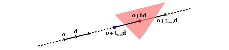
origin and direction naturally refer to the origin and direction of the ray, and Tmin and Tmax define the valid parametric range on which intersections can occur. This can be visualized using the following image taken from the Vulkan documentation:
Finally, the payload, which I found to be the most confusing parameter. The ray payload is a user-defined structure which travels along with the ray, and gets modified by the other shaders in the pipeline. Specifically, "[it] can be accessed for reading and writing by each any-hit shader invoked along the ray, and by the miss or closest-hit shader at the end of the query." Notice that intersection shaders are not listed among these. The value we pass in to the actual traceRayEXT() function is an int which points to the payload's location. For example, suppose we want our payload to keep track of just the final color. We could do so as follows:
// Ray Generation Shader
#version 460
#extension GL_EXT_ray_tracing : require

struct MyPayload {
    vec3 color;
};

layout(set = 0, binding = 0) uniform accelerationStructureEXT tlas;
layout(set = 0, binding = 1, rgba8) uniform image2D image;
layout(location = 0) rayPayloadEXT MyPayload payload;

void main() {
    // ...
    // Compute ray parameters like origin and direction
    // ...
    traceRayEXT(
        tlas,
        gl_RayFlagsOpaqueEXT, // Geometries behave as if they were opaque,
        0xff, // no culling
        0,
        0,
        0,
        origin,
        0.1,
        direction,
        100.0,
        0 // location of payload
    );

    imageStore(image, ivec2(gl_LaunchIDEXT.xy), vec4(payload.color, 1.0));
}
Notice that we assign our custom MyPayload instance to location 0, and then pass in 0 as the last parameter of traceRayEXT(). Obviously, this example is a bit contrived, since if we wanted just the color we could pass it in as a vec3 in the layout line instead of creating a MyPayload wrapper around it. This payload must also exist at the same location in any of the other shaders that might be expected to populate it. For example, a closest-hit shader:
// Closest-hit Shader
#version 460
#extension GL_EXT_ray_tracing : require

struct MyPayload {
    vec3 color;
};

layout(location = 0) rayPayloadInEXT MyPayload payload;

void main() {
    payload.color = vec3(1.0, 0.0, 0.0);
}
Pay attention to the fact that the EXT changed from rayPayloadEXT to rayPayloadInEXT. If we reach this closest-hit shader, then by the time the traceRayEXT() returns, the payload struct will be populated with the color red, which we can store in our image.
Quite simple, right? The ray generation shader just needs to call the code to spawn a ray with a given TLAS. Moving on.
Spawning Multiple Rays
We never have to manually dispatch the ray generation shader, but rather we make a call to vkCmdTraceRaysKHR() which handles tracing the rays for us. The function looks like this:
// Provided by VK_KHR_ray_tracing_pipeline
void vkCmdTraceRaysKHR(
    VkCommandBuffer                             commandBuffer,
    const VkStridedDeviceAddressRegionKHR*      pRaygenShaderBindingTable,
    const VkStridedDeviceAddressRegionKHR*      pMissShaderBindingTable,
    const VkStridedDeviceAddressRegionKHR*      pHitShaderBindingTable,
    const VkStridedDeviceAddressRegionKHR*      pCallableShaderBindingTable,
    uint32_t                                    width,
    uint32_t                                    height,
    uint32_t                                    depth
);
commandBuffer is the command buffer where the command will be recorded, and width, height, and depth are the dimensions of the ray trace query. Where this gets interesting is the remaining parameters, which are addresses that point to different regions of the SBT. We have one for the ray generation region, one for the miss shader region, one for the hit shader region (which includes closest-hit, any-hit, and intersection shaders), and one for the callable shader region. These addresses are passed in as VkStridedDeivceAddressRegionKHR, which looks as follows:
// Provided by VK_KHR_ray_tracing_pipeline
typedef struct VkStridedDeviceAddressRegionKHR {
    VkDeviceAddress    deviceAddress;
    VkDeviceSize       stride;
    VkDeviceSize       size;
} VkStridedDeviceAddressRegionKHR;
VkDeviceAddress is the device address where the region starts, but can optionally be set to 0 if the region is unused. The stride parameter here is measured in bytes, and should ALWYAYS be queried from the physical device properties, instead of being hardcoded. This is done with a call to VkPhysicalDeviceRayTracingPipelinePropertiesKHR(). The size field can simply be your stride multiplied by the number of shaders of that type you have.
Acceleration Structure Instances
You'll recall there's one final place where we get offsets into the SBT: the acceleration structure instances. I will assume you already know how TLASes and BLASes work, and will instead just focus on how Vulkan implements them. We can create a BLAS instance using the VkAccelerationStructureInstanceKHR struct:
// Provided by VK_KHR_ray_tracing_pipeline
typedef struct VkAccelerationStructureInstanceKHR {
    VkTransformMatrixKHR          transform;
    uint32_t                      instanceCustomIndex:24;
    uint32_t                      mask:8;
    uint32_t                      instanceShaderBindingTableRecordOffset:24;
    VkGeometryInstanceFlagsKHR    flags:8;
    uint64_t                      accelerationStructureReference;
} VkAccelerationStructureInstanceKHR;
transform specifies where and how the BLAS instance is positioned in the TLAS. instanceCustomIndex is a user-defined geometry index associated with the BLAS. For example, it can represent a material index. mask is the instance cull mask which is used in conjunction with the traceRayEXT() cull mask as explained earlier. instanceShaderBindingTableRecordOffset is an offset into the hit-group records in the SBT. flags is a bit-mask of VkGeometryInstanceFlagBitsKHR values. Some examples of what you can set this to are VK_GEOMETRY_INSTANCE_TRIANGLE_FACING_CULL_DISABLE_BIT_KHR which just disables front/back-face culling for this instance and VK_GEOMETRY_INSTANCE_FORCE_OPAQUE_BIT_KHR which treats the geometry as opaque, regardless of the geometry's opacity configuration. Finally, the accelerationStructureReference is the address of the BLAS that this instance refers to. This is commonly retrieved with a call to vkGetAccelerationStructureDeviceAddressKHR().
SBT Hit-Group Index Calculation
To recap, let's go through all the different values we've seen so far.
-
vkCmdTraceRaysKHR():
- Starting device address of hit-group (start)
- Stride (in bytes) between entries in the hit-group section (stride)
-
VkAccelerationStructureInstanceKHR{}
- Offset into the hit group records in SBT (instanceOffset)
- A user-defined geometry index (geometryIndex)
-
traceRayEXT()
- Offset into the hit-group record for the ray (traceRayOffset)
- A stride which selects a record based on ray type (traceRayStride)
Putting it all together, we can calculate the hit-group index with the following formula, as defined in this Vulkan Page:
hitGroupRecordAddress = start + stride * (instanceOffset + traceRayOffset + (geometryIndex * traceRayStride))
While this may seem daunting at first, it becomes quite simple if you break it down. It should be fairly straightforward that our final record address will be the starting address (start) plus the stride (stride) multiplied by some number.
Let's simplify things for a moment and suppose that each of our BLASes only contain a single geometry (this is rarely the case). In this hypothetical scenario, each time we trace a ray we essentially need to answer 2 questions:
- Which BLAS instance am I hitting?
- What type of ray am I tracing?
With that in mind, let's look at our formula again. Question 1 is answered by instanceOffset, it gives us the offset for our BLAS instance. Question 2 is answered by traceRayOffset, which gives us the offset for the specific ray type that we're tracing.
Let's do an example. Suppose that we're still considering simple BLASes that only have 1 geometry. Let's say that our TLAS only consists of 4 BLAS instances, and that we trace 3 different ray types: primary rays (traceRayOffset = 0), reflection rays (traceRayOffset = 1), and refraction rays (traceRayOffset = 2). Let's say we set up our SBT like this:

Note that the diagram simplifies each entry of the SBT by denoting it with a single box, even though it may contain multiple shaders as described earlier. The numbers inside the boxes represent what we multily stride by to get the final address. Let's consider how we would find the hit-group address for a refraction ray for instance 2. When making instance 2 host-side, we would have to set the instanceOffset to 6, and when calling traceRayExt(), we would have to set traceRayOffset to 2. This would correctly sum up to a value of 8, which is exactly where we expect the refraction ray shaders for instance 2 to sit. However, this isn't the only way we could've arranged our SBT. Consider, for example:

I've color-coded primary ray shaders in red, reflection in blue, and refraction in green to make this easier to follow. To get the same shaders as earlier (refraction for instance 2), consider what we would have to do. When setting instanceOffset, we can just set it equal to the instance number, but for traceRayOffset we would have to pass in 0 for primary rays, 5 for reflection rays, and 10 for refraction rays. Let's double check: for refraction rays on instance 2, we would have 2 + 10 = 12, which correctly points to where we would expect the shaders to sit. You'll notice that it's a completely different address from what we calculated in the previous SBT.
Now let's consider a more realistic scenario where BLASes consist of multiple geometries. Johannes Unterguggenberger gives the example of a tree BLAS which might have different geometries for its trunk and its leaves. This is exactly what the geometryIndex and traceRayStride values allow us to do. traceRayStride answers the following question: How many SBT records do I need to jump to get from one geometry's ray type group to the next geometry's group? This will make more sense in a moment. geometryIndex is simply the index of the geometry we're concerned with in a BLAS instance.
With that in mind, let's do a more complicated example. Suppose our TLAS consists of a car on the road. The car will be once BLAS instance, and the road will be another. Our (rather simplified) car instance will have 3 geometries: the windows, the body, and the wheels. Windows will account for primary, reflection, and refraction rays. The body of the car will only account for primary and reflection rays. The wheels of the car need only account for primary rays, as wheels are neither reflective nor refractive. Our road instance will only need to account for primary rays. You can imagine one way we could set up our SBT is as follows:

To get the offset for car window refraction shaders, we would use the following calculation (assuming our hit-group start index is 0, and our stride is 32 bytes):
hitGroupRecordAddress = start(0) + stride(32) * (instanceOffset(0) + traceRayOffset(2) + (geometryIndex(0) * traceRayStride(3)))
The values for start and stride should be obvious. The instanceOffset for the car is 0, and for the road is 9. traceRayOffset for primary rays is 0, for reflection rays is 1, and for refraction rays is 2. We chose to define geometryIndex as follows: For the car, geometry 0 is the windows, geometry 1 is the body, and geometry 2 is the wheels. The road only has one geometry at index 0. Finally, the traceRayStride is the number of entries between each geometry's ray type group. As you can see, there are 3 entries between the primary ray shaders for each geometry, just as there are 3 entries between the reflection and refraction ray shaders.
You'll also notice that we added some padding to our SBT in order to make our calculations easier to understand. This does not have to be the case, as you may see in Johannes Unterguggenberger's example. Try to watch along and see how he designs his SBT.
SBT Miss Index Calculation
The formula for calculating the miss index is MUCH easier than the one for calculating the hit-group index. It only depends on the following:
-
vkCmdTraceRaysKHR():
- Starting device address of hit-group (start)
- Stride (in bytes) between entries in the hit-group section (stride)
traceRayEXT()
- Index which selects which miss shader to invoke (missIndex)
The formula looks very similar:
missRecordAddress = start + stride * missIndex
Due to how straightforward this is compared to the hit-group index calculation, I will not be giving any examples of this. You're encouraged to watch Johannes Unterguggenberger's example if you're having trouble.
Closing Remarks
The Vulkan ray tracing pipeline can be a bit confusing if you aren't familiar with how modern graphics APIs (such as DX12) approach ray tracing. If you have a basic understanding of ray tracing, I hope the information in this page cleared up how it works in Vulkan.
Additional resources: